I finally completed my first “major” Arduino project which I’m dubbing iShutter. Here’s the scenario:

The problem is that at Willow Creek Community Church, a large church with a theater-like stage, often uses a center rear-projection screen for graphical elements during the services. However, this screen is on a motorized batten so that during portions of the service where the screen is not needed, it is flown/raised out of sight, and lowered back in when needed.
However, the projectors sit on the ground at the rear of the stage. The problem here is that when the screen is raised, if the projectors are not disabled/shuttered, the projection image will be projecting into everyone’s eyes…a quite undesirable scenario. This shuttering of the projectors has been done manually up till now, but alas, Arduino to the rescue.

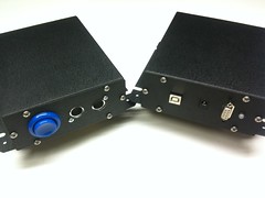
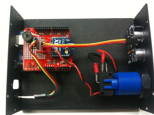
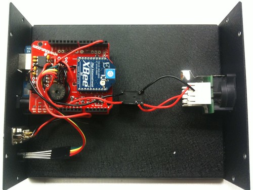
Introducing iShutter. This consists of 2 Arduino Unoscommunicating to each other using the XBee chip. In a nutshell, the transmit module attaches to the side of the projection screen and uses the PING Ultrasonic sensor aimed towards the ground to detect when the screen is at it’s lower limit. Once this threshold has been passed, the transmit module then tells the receiver module to communicate via RS232 to the projector whether to open or close it’s shutter. A button on the transmit box allows users to set the threshold limit.
So, screen lowers in, projector turns on. Screen raises out, projector turns off.
Features:
- Wireless Transmission between two Arduino Uno control boards
- 9v Powered Screen/Transmit Module
- Audio Module to confirm threshold set (plays C chord on Transmit module, followed by a D chord on the receiver module to confirm communication)
- LED Status Indicator (On TX and RX): Blue (Shutter Closed), Green (Shutter Open), Red (Threshold Not Set)
- RS232 to Projector – Projector Specific RS232 code to talk directly to device
- Relay Output of Status – Via Cat5, cabling travels 300ft form receiver module to Video Director to indicate tally of whether projector shutter is open/closed


Learnings:
- To help increase battery life on the transmitter module, I added the sleepPin logic to put the XBee to sleep when not in use, and only fire it up when a transmission is needed to be sent.
- Had to dumb down the sensitivity of the PING ultrasonic sensor as it is extremely sensitive!
- Needed to get a converter chip for RS232 to transmit the proper RS232 voltage so that the projector would see correct RS232!
- Aluminum enclosures, while sexy looking, seriously decreases the wireless transmission distance! Sad – had to leave the covers off of the enclosures so that the wireless transmission would be solid.
Transmitter Arduino Code
const int pingPin = 7;
const int buzzerPin = 6;
const int buttonPin = 2;
const int redLedPin = 11;
const int greenLedPin = 10;
const int blueLedPin = 9;
const int sleepPin = 3;

long triggerDistance = 0;
long curDistance = 0;
boolean shutterOpen = false;
int closeTolerance = 0;
int openTolerance = 0;
int pingAliveCount = 0;
long pingCount = 0;

void setup() {
  // initialize serial communication:
  Serial.begin(9600);
  pinMode(sleepPin, OUTPUT);
  pinMode(buzzerPin, OUTPUT);
  pinMode(buttonPin, INPUT);
  LED(64,0,0);
  digitalWrite(sleepPin, HIGH);
}

void loop()
{
  if(digitalRead(buttonPin) == LOW) {
    digitalWrite(sleepPin, LOW);
    delay(15);
    Serial.print(49, BYTE);
    delay(10);
    Serial.print(10, BYTE);
    delay(10);
    digitalWrite(sleepPin, HIGH);
    setTriggerDistance();
    successSound();
    openShutter();
  }
  curDistance = getDistance();
  if(curDistance > triggerDistance && shutterOpen && closeTolerance > 0) {
    closeShutter();
  } else if ( curDistance <= triggerDistance && shutterOpen != true && openTolerance > 0) {
    openShutter();
  } else if (curDistance > triggerDistance && shutterOpen) {
    closeTolerance++;
  } else if (curDistance <= triggerDistance && !shutterOpen) {
    openTolerance++;
  } else {
    openTolerance = 0;
    closeTolerance = 0;
  }
  delay(500);
}

void setTriggerDistance() {
  triggerDistance = getDistance();
  LED(0,64,0);
}
void openShutter() {
 digitalWrite(sleepPin, LOW);
 delay(15);
 Serial.print(50, BYTE);
 delay(10);
 Serial.print(10, BYTE);
 delay(10);
 LED(0,64,0);
 shutterOpen = true;
 openTolerance = 0;
 closeTolerance = 0;
 digitalWrite(sleepPin, HIGH);
}
void closeShutter(){
 digitalWrite(sleepPin, LOW);
 delay(15);
 Serial.print(51, BYTE);
 delay(10);
 Serial.print(10, BYTE);
 delay(10);
 LED(0,0,64);
 shutterOpen = false;
 openTolerance = 0;
 closeTolerance = 0;
 digitalWrite(sleepPin, HIGH);
}
void successSound(){
    tone(buzzerPin, 523, 200);
    delay(100);
    tone(buzzerPin, 659, 200);
    delay(100);
    tone(buzzerPin, 783, 200);
    delay(100);
    tone(buzzerPin, 1046, 200);
    delay(100);
    noTone(6);
}

long getDistance(){
  long distance;

  // The PING))) is triggered by a HIGH pulse of 2 or more microseconds.
  // Give a short LOW pulse beforehand to ensure a clean HIGH pulse:
  pinMode(pingPin, OUTPUT);
  digitalWrite(pingPin, LOW);
  delayMicroseconds(2);
  digitalWrite(pingPin, HIGH);
  delayMicroseconds(5);
  digitalWrite(pingPin, LOW);

  // The same pin is used to read the signal from the PING))): a HIGH
  // pulse whose duration is the time (in microseconds) from the sending
  // of the ping to the reception of its echo off of an object.
  pinMode(pingPin, INPUT);
  distance = pulseIn(pingPin, HIGH);

  return distance / 512;
}

void LED(int red, int green, int blue) {
  analogWrite(redLedPin, red);
  analogWrite(greenLedPin, green);
  analogWrite(blueLedPin, blue);
}
Receiver Arduino Code
const int tallyPin = 5;
const int buzzerPin = 6;
const int redLedPin = 11;
const int greenLedPin = 10;
const int blueLedPin = 9;
int mode;

void setup() {
  Serial.begin(9600);
  pinMode(tallyPin, OUTPUT);
  pinMode(buzzerPin, OUTPUT);
  LED(20,0,0);
}

void loop()
{
  while(Serial.available()){
    int mode = Serial.read() - '0';
    switch(mode) {
      case 1:
         successSound();
         openShutter();
         break;
      case 2:
         openShutter();
         break;
       case 3:
         closeShutter();
         break;
  }
  Serial.flush();
  }
}
void openShutter() {

 Serial.print(0xfe, BYTE);
 Serial.print(0x01, BYTE);
 Serial.print(0x22, BYTE);
 Serial.print(0x42, BYTE);
 Serial.print(0x00, BYTE);
 Serial.print(0x65, BYTE);
 Serial.print(0xff, BYTE);
 Serial.print(0x0a, BYTE);
 LED(0,20,0);
 digitalWrite(tallyPin, HIGH);
}
void closeShutter(){
 Serial.print(0xfe, BYTE);
 Serial.print(0x01, BYTE);
 Serial.print(0x23, BYTE);
 Serial.print(0x42, BYTE);
 Serial.print(0x00, BYTE);
 Serial.print(0x66, BYTE);
 Serial.print(0xff, BYTE);
 Serial.print(0x0a, BYTE);
 LED(0,0,20);
 digitalWrite(tallyPin, LOW);
}
void successSound(){
    delay(500);
    tone(buzzerPin, 587, 200);
    delay(100);
    tone(buzzerPin, 740, 200);
    delay(100);
    tone(buzzerPin, 880, 200);
    delay(100);
    tone(buzzerPin, 1174, 200);
    delay(100);
    noTone(6);
}

void LED(int red, int green, int blue) {
  analogWrite(redLedPin, red);
  analogWrite(greenLedPin, green);
  analogWrite(blueLedPin, blue);
}
More Photos
You can view more photos on the Flickr set.
This content will be shown after all post